


Sparx Systems Enterprise Architect
Why Component Diagram Modeling Matters in UML
After defining the logical structure of the system using Class Diagrams, the next step in disciplined software architecture is understanding how the system is organized into modular components and how those components interact.
UML Component Diagrams provide a structured way to represent the physical organization of software systems. They illustrate how software modules, services, and subsystems collaborate to deliver system functionality.
Within Sparx Enterprise Architect, Component Diagrams serve as a bridge between system design and implementation. They help architects define modular architecture, establish clear interfaces, and ensure that software systems remain scalable and maintainable.
Identifying Components from System Design
Component modeling begins by analyzing the system architecture and identifying the major building blocks that make up the solution.
These typically include:
- Components – deployable modules such as services, libraries, or subsystems.
- Interfaces – contracts that define how components communicate with each other.
- Dependencies – relationships that indicate how components rely on other components.
In Sparx Enterprise Architect, components can be linked to requirements, Use Cases, and Class models, ensuring traceability across the entire software architecture. This alignment ensures that each component contributes directly to fulfilling system functionality.
Understanding Component Relationships
UML provides several constructs that define how components interact within the system architecture.
- Provided Interfaces
Represent the services that a component offers to other components. - Required Interfaces
Represent the services that a component needs from other components. - Dependencies
Show how one component relies on another component for functionality or data.
Interfaces and Component Communication
Interfaces play a critical role in Component Diagrams by defining how components interact.
- Provided Interfaces specify the services a component exposes.
- Required Interfaces specify the services a component consumes.
By clearly defining interfaces, architects ensure that components can evolve independently while maintaining compatibility with the overall system architecture.
In Sparx Enterprise Architect, these interfaces can be reused across multiple components, improving architectural consistency.
Benefits of UML Component Diagram Modeling in Sparx Enterprise Architect
- Clear visualization of modular system architecture
- Improved separation of concerns between system modules
- Better communication between architecture and development teams
- Strong traceability between architecture layers
- Easier system integration and maintenance
By combining UML standards with EA’s modeling capabilities, organizations can design scalable, maintainable, and well-governed software systems.
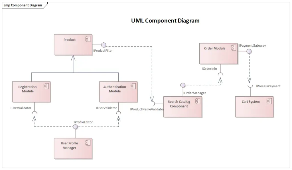
Figure 1: UML Component Diagram Modeling in Sparx EA
Accelerate Component Modeling with Sparx Systems India
Sparx Systems India supports organizations in implementing effective UML Component Diagram modeling practices using Sparx Enterprise Architect through:
- UML component modeling framework setup and repository configuration
- Software architecture and modular design best-practice consulting
- Hands-on UML training for architects, analysts, and development teams
- Prolaborate demos for collaborative architecture visualization and stakeholder reviews
To explore how UML Component Diagram modeling in Sparx Enterprise Architect can strengthen your modular software architecture and enable scalable, traceable system design, write to us at sales@sparxsystems.in, or contact us to get started.