


Sparx Systems Enterprise Architect
Why Sequence Modeling Matters in UML
After defining workflows using Activity Diagrams, the next step in disciplined behavioral modeling is understanding how system components interact over time.
UML Sequence Diagrams provide a structured way to model message flow, interaction logic, and execution order between system elements. They ensure that system behavior is correctly sequenced and aligned with functional requirements.
Within Sparx Enterprise Architect, Sequence Diagrams act as a bridge between workflows and implementation logic, helping teams validate interactions before development begins.
Identifying Sequence Elements from System Requirements
Sequence modeling begins by analyzing requirements and identifying how system components communicate during execution.
These elements typically include:
- Lifelines – objects or components participating in the interaction.
- Messages – communication exchanged between lifelines.
- Execution Flow – the order in which interactions occur over time.
In Sparx Enterprise Architect, these elements can be linked to Use Cases, Classes, and Components, ensuring end-to-end traceability across the system lifecycle.
Understanding Sequence Diagram Elements in Sparx EA
Sparx Enterprise Architect provides a rich Interaction toolbox to model sequence behavior effectively.
Key elements include:
- Actor
Represents external users or systems interacting with the solution. - Lifeline
Defines participants (objects, services, or components) involved in the interaction. - Boundary
Represents system interfaces such as UI or external system boundaries. - Control
Handles business logic and coordination between components. - Entity
Represents data objects or persistent entities. - Message
Defines communication between lifelines, including synchronous and asynchronous calls. - Fragment
Models control logic such as conditions (alt), loops (loop), and parallel execution (par). - State / Continuation
Represents continuation points or state references within interactions. - Diagram Gate
Used to manage interaction flow across diagrams or define entry/exit points.
Modeling Message Flow and Execution Order
Sequence Diagrams focus on time-based interaction and communication logic.
- Synchronous Messages – represent blocking calls waiting for completion.
- Asynchronous Messages – allow parallel execution without waiting.
- Return Messages – represent responses between components.
Using combined fragments, architects can model:
- Conditional flows (alt)
- Loops (loop)
- Parallel execution (par)
In Sparx Enterprise Architect, these capabilities ensure that system interactions are logically complete and aligned with architecture design.
Benefits of UML Sequence Modeling in Sparx Enterprise Architect
- Clear visualization of system interactions over time
- Improved validation of message flow and execution logic
- Strong alignment between workflows and implementation
- Better communication between architects and developers
- Early identification of integration and interaction issues
By combining UML standards with EA’s modeling capabilities, organizations can design robust, interaction-driven system behavior.
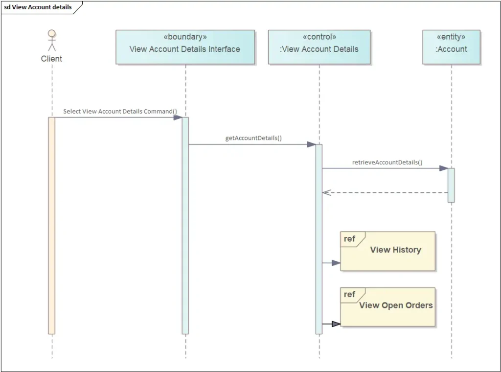
Figure 1: UML Sequence Diagram in Sparx EA
Accelerate Sequence Modeling with Sparx Systems India
Sparx Systems India supports organizations in implementing effective UML Sequence Modeling using Sparx Enterprise Architect through:
- Sequence modeling framework setup and repository configuration
- Interaction and integration modeling best-practice consulting
- Hands-on UML training for architects, analysts, and development teams
- Prolaborate demos for collaborative interaction visualization
To explore how UML Sequence Modeling in Sparx Enterprise Architect can strengthen system interaction design and enable structured, traceable, and scalable software behavior, write to us at sales@sparxsystems.in or contact us to get started.