


Sparx Systems Enterprise Architect
Leading organizations achieve engineering excellence with high-performance, scalable, and future-ready systems. Model-Based Systems Engineering (MBSE) ensures efficient design, thorough validation, and full traceability. Leveraging SysML in Sparx Systems Enterprise Architect (EA) unifies development, accelerates delivery, and enhances collaboration across aerospace, defense, and automotive domains.
Why MBSE and SysML?
MBSE replaces fragmented, document-driven practices with a connected, model-centric approach. SysML implements MBSE by enabling engineers to represent system structure, behavior, interactions, and requirements within a single unified model. This approach enhances clarity, reduces errors, simplifies complexity management, and fosters seamless collaboration across teams.
Why Choose Enterprise Architect for MBSE?
Sparx Systems Enterprise Architect supports the full spectrum of MBSE practices—from requirement capture to architecture validation and simulation.
Key features include:
- Comprehensive SysML Support: Full SysML 1.5 support (A dedicated SysML 2.0 modeling environment is expected soon in Enterprise Architect)
- Integrated Requirements Management: Capture, trace, and validate requirements directly within the model, or integrate requirements from external tools such as IBM DOORS NG, Jira, and Jama.
- Document Generation: Automatically produce consistent, high-quality reports and system documentation from your models.
- Collaboration Tools via Prolaborate – Share models with business users, get real-time feedback, and track stakeholder input.
- Enable Version Control – Use EA’s built-in Version management features for controlled model evolution.
From Requirements to Behavior: End-to-End MBSE Modeling
Specification Modeling :
Requirements
The foundation of MBSE is capturing and managing system requirements. Using SysML Requirement Diagrams, teams can:
- Organize high-level and detailed requirements hierarchically.
- Differentiate requirements by properties such as status (proposed, approved, etc.) with visual color-coding.
- Import requirements from external tools like Jira, Jama, IBM DOORS, or Polarion, centralizing all data within EA.
Requirements are not isolated—they drive the subsequent modeling process.
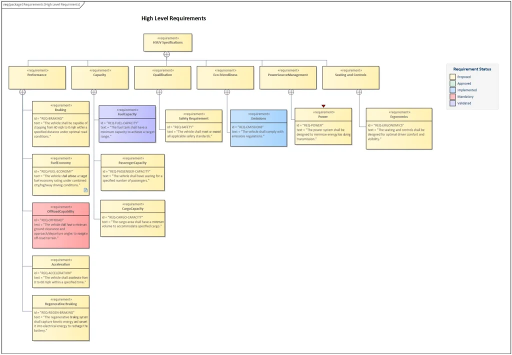
Figure 1: Requirement Diagram in Sparx EA
Use Case
Once requirements are captured, Use Case Diagrams transform them into functional scenarios:
- Present a high-level view of system functionality and interactions with external actors (users, other systems).
- Describe scenarios step-by-step, including alternative and exception paths.
- Define preconditions and postconditions to clarify system expectations.
- Generate Activity Diagrams directly from use cases, visualizing behavior paths effortlessly.
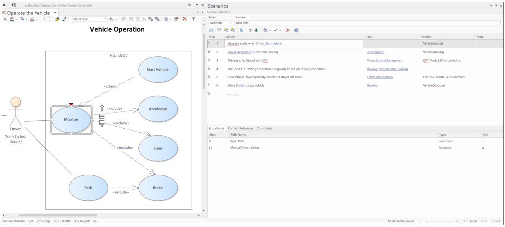
Figure 2: Use Case Diagram in Sparx EA
Structural Modeling :
Block Definition
- Defines system components and subsystems, their properties, operations, and relationships.
- Provides a high-level view of system architecture, showing how blocks connect.
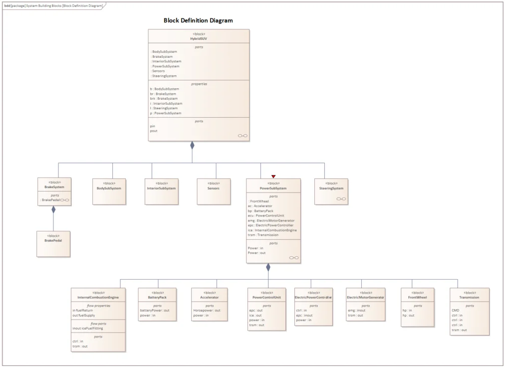
Figure 3: Block Definition Diagram in Sparx EA
Internal Block Diagram
- Details the internal structure of blocks, including parts, ports, and connectors.
- Visualizes how subcomponents interact, offering a deeper understanding of system architecture.
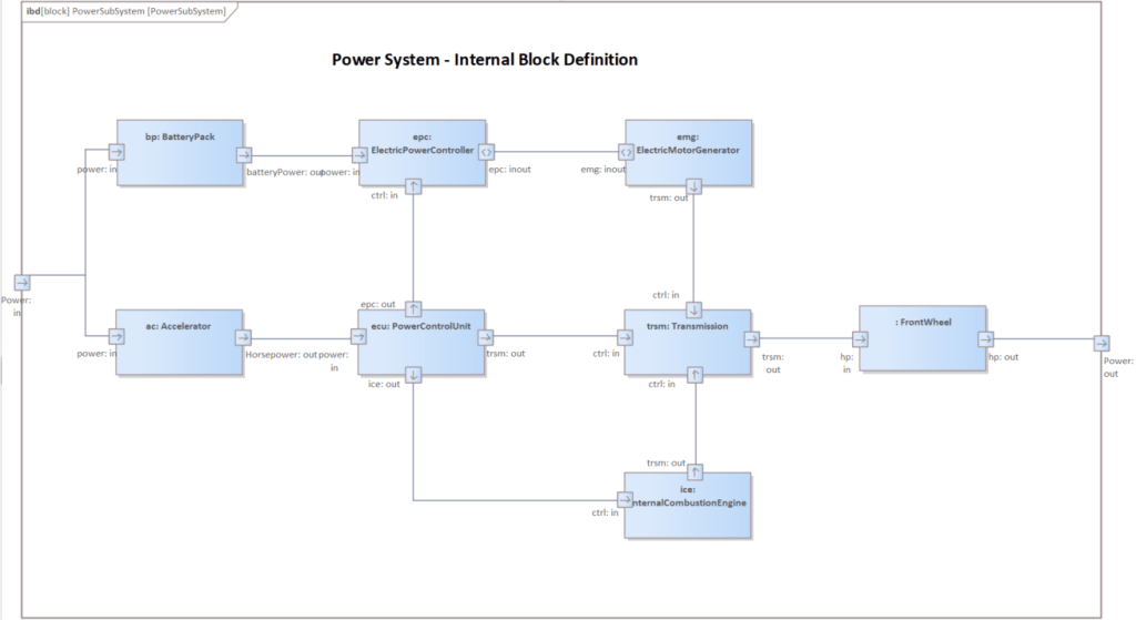
Figure 4: Internal Block Diagram in Sparx EA
Behavioral Modeling :
Activity Diagram
- Models the workflow and processes of the system.
- Activities are often partitioned by actors or system components.
- Allows drilling into detailed workflows to understand system behavior clearly.
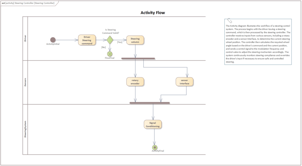
Figure 5: Activity Diagram in Sparx EA
Sequence Diagram
- Illustrates interactions between system elements over time.
- Captures message sequences, loops, alternatives, and parallel paths.
- Validates dynamic behavior and communication order between components.
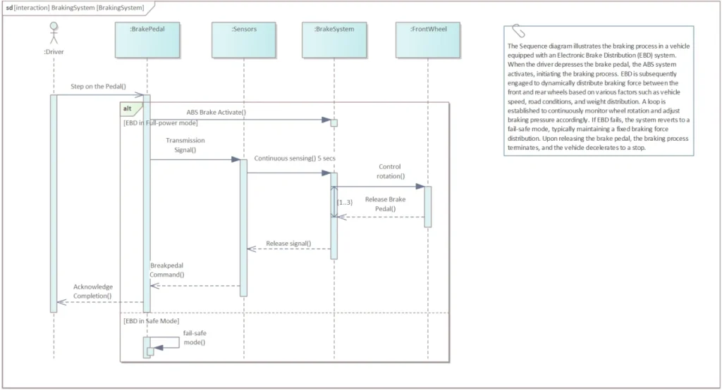
Figure 6: Sequence Diagram in Sparx EA
State Machine
- Models system or component states and transitions in response to events or triggers.
- Define behaviors such as entry, exit, and internal actions.
- Simulate state transitions in EA to visualize system behavior under varying conditions.
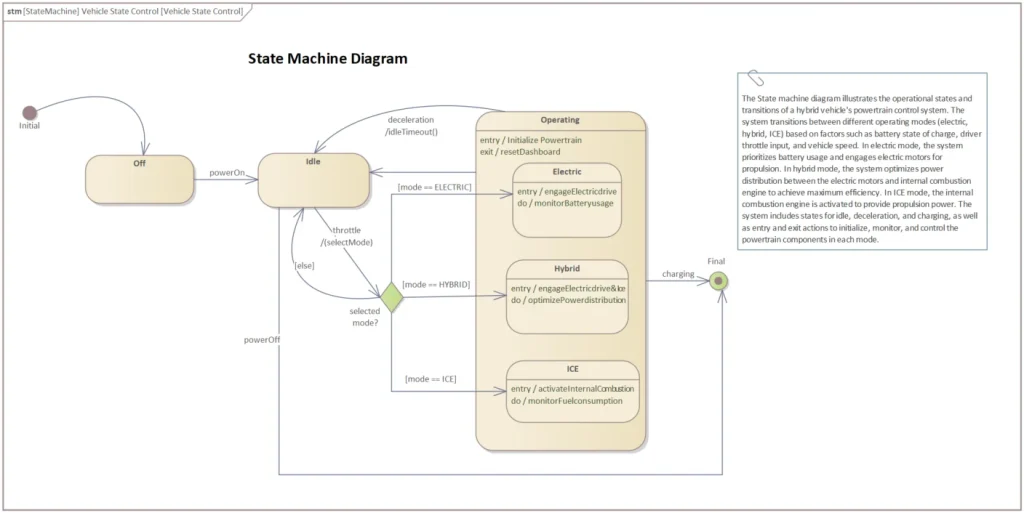
Figure 6: State Machine Diagram in Sparx EA
End-to-End Traceability
All diagrams in MBSE are closely connected, forming a cohesive model:
- Requirements Traceability: Requirements are refined through use cases, verified by test cases, and satisfied by system blocks that encapsulate behavior diagrams as composites.
- Provides full visibility from requirement capture to system behavior, enabling impact analysis and informed decision-making.
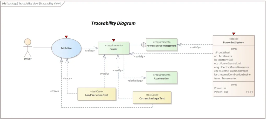
Figure 7: Traceability in Sparx EA
Conclusion
Model-Based Systems Engineering with SysML in Enterprise Architect allows organizations to design, validate, and deliver complex systems efficiently. By adopting a model-centric approach, teams reduce risk, enhance quality, and accelerate time-to-market. EA provides a comprehensive and cost-effective platform to support your MBSE journey from concept to delivery.
Get Started Today!
Unlock the power of Model-Based Systems Engineering (MBSE) with SysML using Sparx Systems Enterprise Architect. Connect with our experts at sales@sparxsystemsindia.6thforce.com, visit www.sparxsystems.in, or reach out via our Contact Us page. Our team is ready to assist with licensing, consulting, training, Prolaborate demos, and premium support to help your organization implement MBSE, streamline system development, and achieve engineering excellence.